This is the second part of a series of articles that I'm writing based on my experiences with my GameBoy emulator written in .NET Core; Retro.Net. This time I'll be having a look at the core of the emulator, which implements a high level form of dynamic recompilation to emulate the Z80 derived GameBoy CPU.
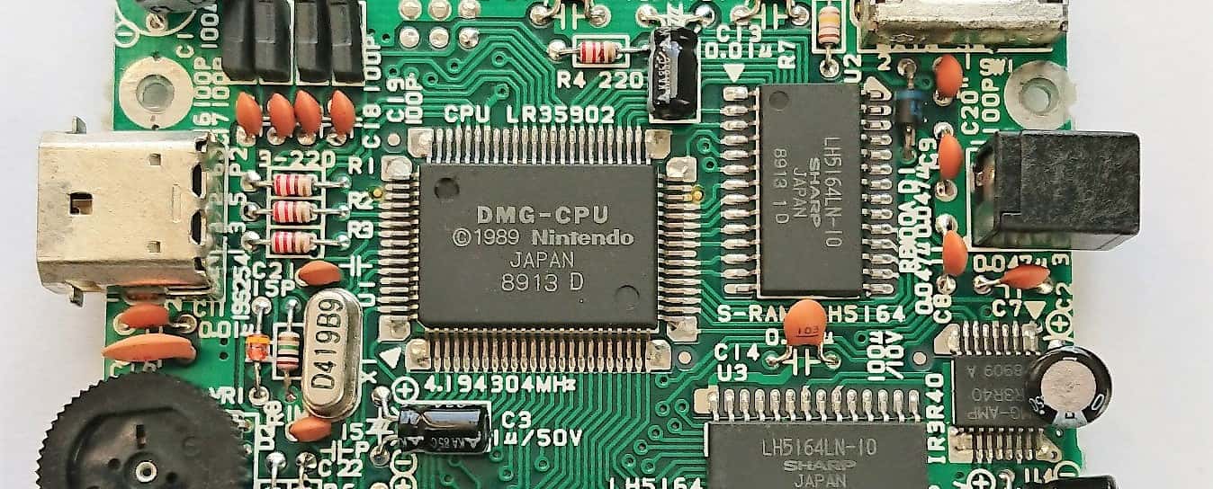
At it's lowest level, a CPU can be represented by a finite state machine, where state is handled by registers and domain by the address space. This model is pretty simple to implement in software as all you need is a mechanism for tracking state and a definition of all possible state transitions. Luckily the GameBoy CPU, a Sharp LR35902, is derived from the popular and very well documented Zilog Z80 - A microprocessor that is unbelievably still in production today, over 40 years after it's introduction.
The Z80 is an 8-bit microprocessor, meaning that each operation is natively performed on a single byte. The instruction set does have some 16-bit operations but these are just executed as multiple cycles of 8-bit logic. The Z80 has a 16-bit wide address bus, which logically represents a 64K memory map. Data is transferred to the CPU over an 8-bit wide data bus but this is irrelevant to simulating the system at state machine level. The Z80 and the Intel 8080 that it derives from have 256 I/O ports for accessing external peripherals but the GameBoy CPU has none - favouring memory mapped I/O instead. Since I found an abundance of Z80 documentation, including non-official, or undocumented behaviours that were discovered by ZX Spectrum developers, I opted to implement an emulator compatible with the full Z80 specification. To achieve Intel 8080 and GameBoy compatibility, which aren't strict logical subsets of the Z80, I simply provide a platform configuration mechanism that can toggle features.
Firstly we need some registers. The Intel 8080 and GameBoy CPU have six 8-bit general purpose registers, an accumulator, flags, stack pointer and program counter. 16-bit access is also provided to each general purpose register and the accumulator and flags registers in sequential pairs. Additionally, the Z80 has two more 16-bit index registers, an alternative set of each general purpose, accumulator and flags registers and a few more bits and pieces.
Register
Size
Purpose
AF
16-bit or two 8-bit
Accumulator (A) and flag bits (F)
BC
16-bit or two 8-bit
Data/address
DE
16-bit or two 8-bit
Data/address
HL
16-bit or two 8-bit
Accumulator/address
SP
16-bit
Stack pointer
PC
16-bit
Program counter
The Z80 defines alternative/banked versions of AF, BC, DE and HL that are accessed via the exchange opcodes and also has some more specialized registers.
The flags register is a single byte that contains a bit-mask set according to the last result. Notice that the GameBoy flags register only uses the most significant 4-bits and does not implement the sign or parity/overflow flag. The least significant bits of the GameBoy flags register are always 0.
8080/Z80 Bit
GameBoy Bit
Name
0
4
Carry
1
6
Subtract
2
-
Parity/Overflow
3
-
Undocumented
4
5
Half Carry
5
-
Undocumented
6
7
Zero
7
-
Sign
The flags registers are implemented slightly differently on each platform so we'll hide them away behind an interface.
public interface IFlagsRegister
{
    byte Register { get; set; }

    bool Sign { get; set; }

    bool Zero { get; set; }

    bool Flag5 { get; set; }

    bool HalfCarry { get; set; }

    bool Flag3 { get; set; }

    bool ParityOverflow { get; set; }

    bool Subtract { get; set; }

    bool Carry { get; set; }
}
For example, we might implement the GameBoy flags register as follows.
public class GameBoyFlagsRegister : IFlagsRegister
{
    private const byte ZeroMask = 1 << 7;
    private const byte SubtractMask = 1 << 6;
    private const byte HalfCarryMask = 1 << 5;
    private const byte CarryMask = 1 << 4;

    public byte Register
    {
        get => (byte) ((Zero ? ZeroMask : 0)
                     | (HalfCarry ? HalfCarryMask : 0)
                     | (Subtract ? SubtractMask : 0)
                     | (Carry ? CarryMask : 0));
        set
        {
            Zero = (value & ZeroMask) > 0;
            HalfCarry = (value & HalfCarryMask) > 0;
            Subtract = (value & SubtractMask) > 0;
            Carry = (value & CarryMask) > 0;
        }
    }

    public bool Sign { get { return false; } set { } }

    public bool Zero { get; set; }

    public bool Flag5 { get { return false; } set { } }

    public bool HalfCarry { get; set; }

    public bool Flag3 { get { return false; } set { } }

    public bool ParityOverflow { get { return false; } set { } }

    public bool Subtract { get; set; }

    public bool Carry { get; set; }
}
public class GameBoyFlagsRegister : IFlagsRegister
{
private const byte ZeroMask = 1 << 7;
private const byte SubtractMask = 1 << 6;
private const byte HalfCarryMask = 1 << 5;
private const byte CarryMask = 1 << 4;
public byte Register
{
get => (byte) ((Zero ? ZeroMask : 0)
| (HalfCarry ? HalfCarryMask : 0)
| (Subtract ? SubtractMask : 0)
| (Carry ? CarryMask : 0));
set
{
Zero = (value & ZeroMask) > 0;
HalfCarry = (value & HalfCarryMask) > 0;
Subtract = (value & SubtractMask) > 0;
Carry = (value & CarryMask) > 0;
}
}
public bool Sign { get { return false; } set { } }
public bool Zero { get; set; }
public bool Flag5 { get { return false; } set { } }
public bool HalfCarry { get; set; }
public bool Flag3 { get { return false; } set { } }
public bool ParityOverflow { get { return false; } set { } }
// Some more Z80 specific stuff omitted for brevity
}
We'll have two implementations of this interface; one for the Z80 and one shared by the GameBoy and Intel 8080. The Z80 implementation will have full functionality whereas the Intel 8080/GameBoy implementation will throw when calling methods or properties that are not supported by the platform. It will be the responsibility of the CPU core implementation to configure the correct level of register support for each platform.
Next we need to implement the memory management unit (MMU) to broker access to the address space. The relationship between CPU, MMU, memory and memory mapped IO devices looks something like the following.
An MMU should support reading and writing data in various lengths across the entire address space, whilst abstracting away the hardware that is physically attached to each location in the space.
public interface IMmu : IDisposable
{
    byte ReadByte(ushort address);

    ushort ReadWord(ushort address);

    byte[] ReadBytes(ushort address, int length);

    void WriteByte(ushort address, byte value);

    void WriteWord(ushort address, ushort word);

    void WriteBytes(ushort address, byte[] bytes);
}
We can implement an MMU in a platform agnostic way by introducing a concept of segments. A segment has a location and length so that the MMU can correctly position it in address space and will provide implementation specific data access operations. For example, most GameBoy cartridges have a microcontroller acting as a memory bank controller (MBC) over multiple banks of read only memory (ROM). Read requests for data in an MBC address space will be forwarded to a configured page of ROM, whereas write requests will change which page is configured. For this reason we really need different interfaces for readable and writeable segments.
public interface IAddressSegment
{
    MemoryBankType Type { get; }

    ushort Address { get; }

    ushort Length { get; }
}
public interface IAddressSegment
{
    MemoryBankType Type { get; }

    ushort Address { get; }

    ushort Length { get; }
}
public interface IReadableAddressSegment : IAddressSegment
{
    byte ReadByte(ushort address);

    ushort ReadWord(ushort address);

    byte[] ReadBytes(ushort address, int length);

    void ReadBytes(ushort address, byte[] buffer);
}
public interface IReadableAddressSegment : IAddressSegment
{
    byte ReadByte(ushort address);

    ushort ReadWord(ushort address);

    byte[] ReadBytes(ushort address, int length);

    void ReadBytes(ushort address, byte[] buffer);
}
public interface IWriteableAddressSegment : IAddressSegment
{
    void WriteByte(ushort address, byte value);

    void WriteWord(ushort address, ushort word);

    void WriteBytes(ushort address, byte[] values);
}
public interface IWriteableAddressSegment : IAddressSegment
{
    void WriteByte(ushort address, byte value);

    void WriteWord(ushort address, ushort word);

    void WriteBytes(ushort address, byte[] values);
}
For example, a very simple segment that represents random access memory (RAM) could be implemented using a byte array:
public class ArrayBackedMemoryBank : IReadableAddressSegment, IWriteableAddressSegment
{
protected readonly byte[] Memory;
public ArrayBackedMemoryBank()
{
Memory = new byte[1024];
Type = MemoryBankType.RandomAccessMemory;
Address = 0x000;
Length = 0x1000;
}
public MemoryBankType Type { get; }
public ushort Address { get; }
public ushort Length { get; }
public byte ReadByte(ushort address) => Memory[address];
public ushort ReadWord(ushort address) => BitConverter.ToUInt16(Memory, address);
public byte[] ReadBytes(ushort address, int length)
A CPU runs on a fetch-decode-execute cycle, called the machine cycle or m-cycle. The CPU will initially fetch a byte, whose location in the address space is pointed to by the program counter register (PC), decode it as an instruction (opcode) and execute it, or contextually use it as a literal for a previous cycle. Opcodes not related to absolute program flow, such as jumps or calls, will end a cycle by incrementing the program counter to point at the next byte in the address space. Opcode length is variable and whilst some operations run in a single cycle, others require multiple fetch-decode-execute cycles to run. Opcodes are specified by the official Zilog Z80 documentation but you must also consider the differences in implementation on the GameBoy CPU. Here's an example of running three simple opcodes on a Z80:
We're not really concerned with this low level cycle as software cannot control it, but we do need to keep track of how many have occurred so that we have a mechanism to match (read: approximate) platform timing. Our higher level cycle will be based on a concept of an operation, which can be represented by one or more opcodes and optional literals.
Each operation cycle will:
Fetch the next opcode.
Decode the fetched opcode.
Fetch any extra data required to resolve the operation including extra opcodes and literals.
Record all m-cycles consumed in the operation so that we can block later to adjust our timings.
// Overflow = (added signs are same) && (result sign differs from the sign of either of operands)
flags.ParityOverflow = ((a ^ b) & 0x80) == 0 && ((result ^ a) & 0x80) != 0;
// Carry = carry from bit 7 to bit 8.
flags.Carry = (result & 0x100) == 0x100;
// We're adding, so unset the subtract flag;
flags.Subtract = false;
// Sign flag is a copy of the sign bit.
flags.Sign = (result & 0x80) == 0x80;
// Set Zero flag if result is 0
flags.Zero = result == 0;
// Undocumented flags are set from corresponding result bits.
flags.Flag5 = (result & 0x20) == 0x20;
flags.Flag3 = (result & 0x8) == 0x8;
return (byte) result;
}
}
We spend the majority of the Add function dealing with flags. This is a common theme of ALU methods so it makes sense that a complete ALU implementation would group flag manipulations into logical groups abstracted away behind methods such as SetResultFlags.
We can do much better than the naive Z80 implementation above. The main issue I have with it is that we are decoding each opcode on every cycle, even if we've already decoded the exact same block of memory in a previous cycle. Since we're all software developers here, we know that the basic building blocks of software are control flow structures such as loops and functions. Software written for the Z80 platform is no different, it also consists of control flow structures, which means that the same code is run many times but against different data or CPU states. An ideal solution to this problem is to recompile Z80 opcodes and static data into a structure suitable for caching. In this case we would run a decode step only once per block of memory, compiling and caching it with enough meta data to recall later. When the CPU core attempts to decode the same block in the future, it will first check the cache. A hit will mean it can skip the entire decode-compile step resulting in a massive boost to performance. We will define block boundaries where an operation changes the program counter directly i.e. program flow opcodes such as jumps, calls, resets and returns. Since we're using .NET we have the expression tree API; a brilliant abstraction over emitting IL. Here's an example of how we might improve the original naive example to use cached expression trees.
The examples presented here have obviously been bastardised to fit onto a blog post, demonstrating a concept or technique rather than providing a complete implementation. For example, the ExpressionTreeZ80 above fails to consider timing or self modifying code, misses out on some simple optimizations such as a pre-fetch queue and fails to consider unit testability by not separating the decode and execute steps. For the full implementation please visit Retro.Net on GitHub.